Cat5, Cat5e and Cat6 standards of network cabling are commonly used for computer networks but can also be used for other purposes such as telephone, and video. They were originally rated at 10Mb, 100Mb and 1Gb respectively but the limits have all been pushed.
The cable
The cable itself consists of four twisted pairs of wires. By convention these are numbered 1 = Blue (Bl), 2 = Orange (Or), 3 = Green (Gr) and 4 = Brown (Br). Each pair has one wire in a solid colour and one striped with white and the important feature is the twisting which gives it the high bandwidth and low cross talk characteristics. Normally this will be unshielded though shielded and individually screened are sometimes seen in hostile conditions. The difference for Cat6 is that the pairs are separated in the cable by a plastic cross partition, the wiring is the same. No connection should be more than 100m long with (ideally) no more than 10m of that being patch cables. There should be no kinks with bends with a radius of no less than 25mm. Use Velcro cable ties if possible as the normal ratchet ones squeeze the cables too tightly.
The connectors
 The connectors are flat and latched on the wide face, called RJ45 (unlike UK telephone plugs which are latched on the short edge). There are variations for each Cat level so be sure to get the right type. Looking at the top (flat) face with the cable towards you, the pins are numbered 1 to 8 from the left. It is important that the twists in the pairs are maintained as close as possible to the connectors.
The T568B standard is the most common wiring pattern, and that is what I will assume for this article.The A version of the standard interchanges pairs 2 and 3 (orange and green). T568A can be used so long as you are consistent within any one installation and the standards people say that the A scheme should be used for all new installations but everyone seems to ignore them. Pre-made patch cables are invariably to the B scheme but, as I said before, it still doesn’t matter which you use so long as each run is the same both ends. See how your patch panels are wired before deciding.
The T568B pattern
pair 2    pair 3    pair 1    pair 4
W/Or Or   W/Gr Gr   W/Bl Bl   W/Br Br
1    2    3    6    5    4    7    8
Looking at the top of the plug, this comes out as
W/Or Or   W/Gr Bl   W/Bl Gr   W/Br Br
1    2    3    4    5    6    7    8
 Sockets vary in how they are set up. many should be connected
Or   W/Or W/Gr W/Bl Bl   Gr   Br   W/Br
2    1    3    5    4    6    8    7
 The reason for the difference is that there are internal twists inside to maintain the performance. Others use punch-down blocks like the patch panels below. For T568A conventions, interchange the orange and green pairs in all of the above.
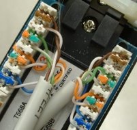 Patch-panels often use a punch-down block with coloured markers. The striped wire goes first (on the left) when in the normal BLOG order (BLue, Orange, Green, brown). Again, the internal wiring sorts out the order on the pins.
pair 1    pair 2    pair 3    pair 4
W/Bl Bl   W/Or Or   W/Gr Gr   W/Br Br
5    4    1    2    3    6    7    8
Cross-over
Normal patch cables are wired straight through, pin 1 to pin1, pin 2 to pin 2 etc. For Ethernet, pair 2 is send and pair 3 receive and this allows computer to be connected to a hub or switch. A cross-over cable reverses the send and receive pairs so that connections computer to computer or switch to switch can be made directly. The plug on one end is wired as follows (coincidentally this is also the T568A pattern)
W/Gr Gr   W/Or Bl   W/Bl Or   W/Br Br
1    2    3    4    5    6    7    8
If you are using (or planning) Gb Ethernet then your cross-over cables will also need to reverse pairs 1 and 4. Cross-over cables are often not needed as much equipment has a cross-over button or a special uplink socket or, now auto-senses and changes over automatically.
W/Gr Gr   W/Or Br   W/Br Or   W/Bl Bl
1    2    3    4    5    6    7    8
Fixed wiring, sockets and patch-panels should never be wired cross-over fashion, it will only confuse people.
Some special use connection patterns
10Mb and 100Mb (fast) Ethernet only uses pairs 2 and 3 (orange and green). Power-over-Ethernet uses pair 1 (blue) as the +ve and pair 4 (brown) as the -ve up to about 13W in the standard wiring configuration. Gb Ethernet uses all four pairs so power-over-Ethernet is not possible with this. No special connections are required.
Analogue telephone over Cat5 uses pairs 1 and 2. I have seen it suggested that a single cable can be split to use two pairs for Ethernet and the other two (pairs 1 and 4) for telephone but I wouldn’t recommend it. Use RJ45 throughout with standard connections and adapters for phone use if required. Pins 2 and 5 (on the telephone plug) are the signal, pin 3 is the bell and pin 4 ground. Pins 1 and 6 exist but are only used for PBX digital lines.
1    2    3    4    5    6    7    8 RJ45
|    |    |    |    |    |    x    x
4    3    6    2    5    1           BT type socket
If you are short of cable outlets then you can get special adaptors to run Ethernet and telephone over the same wire – but they are expensive! Note that, for some unaccountable reason, BT plugs number in reverse order to the sockets.
ISDN connections are the same as for Ethernet but I don’t know what pairs they use.
VGA and Video over Cat5 is now cost effective for those longer runs and requires a matched pair of adapters, often powered at at least one end. Standard wiring connections are used.
Finally one that you won’t come across, but I happen to need—Sun Netra and Cisco Serial console connection (plug), the other end of the patch lead being standard order.
Br   W/Gr Gr   Bl   W/Or W/Bl Or   W/Br
1    2    3    4    5    6    7    8


 Webmaster
The rationale is that cabling will last at least 10 years and will support at least four to five generations of equipment during that time. If future equipment running at much higher data rates requires better cabling, it will be very expensive to pull out category 5e cabling at a later time to install category 6 cabling.