 In the computing, telecoms and professional audio/video business the 19″ rack is ubiquitous for mounting equipment. This standard, named after the equipment size, came originally from the cabinets used to house telephone switchgear and has resisted metrication largely due to the dominance of the USA in computing. There is however enough slack in the dimensions to allow a fairly crude conversion to metric units though you do come across modules that are a bit “tight” when mixed with others.
The fundamental dimensions are the overall width to the outside edge of the flanges which is 19″ and a height, edge-to-edge, of a multiple of 1¾”. This height is known as 1 unit or 1U so pieces of equipment are specified as, for example, 3U which is 5¼”. The standard actually says that every item (however large) should be 1/32″ shorter to allow for clearance but this can be ignored unless you are manufacturing them.
The flanges (or ears) have holes for bolting to the rack rails and the horizontal distance between centres is 18 5/16″ though the holes are usually drilled oval which allows quite a bit of sideways movement. For a neat effect you should loosen the screws a little after installation align the units before final tightening. The minimum clearance between the rails and other obstructions should be 17 ¾” though some are a very close fit.
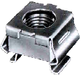 The fixings are most commonly M6 cheese-head bolts (in Europe) and corresponding “cage-nuts” inserted into the 3/8″ square cut-outs in the rails. You do sometimes see drilled and tapped rails but this is usually on proprietary racks used by the bigger computer manufacturers. The rails can either be steel or aluminium and it should be noted that they require different cage-nuts to allow for the metal thickness. The bolts are usually steel and plastic washers can be used to protect the finish. If earth isolation is required then nylon bolts (for light equipment) or plastic flange washers are available, but otherwise it is general practice to earth the rails with a strap.
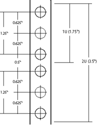 The hole spacing on the rail is complex. Each U has provision for three holes, though the middle one is rarely used. The spacing to the centres from the top or bottom of the unit is ¼”, 7/8″ and 1½”. This means that they are uneven, some being ½” apart and others 5/8″, making it VERY important that units are correctly located in their proper U positions, not offset by one or two holes. To help with this, many rails have a small notch cut out of the edge of the central square hole in each group to identify it. The cage nuts allow a small amount of vertical movement which may be needed when installing fractionally oversize modules.
The smaller equipment (up to 3U) is usually secured by two bolts on each side. 1U and 2U cases usually use the outer hole positions, 3U cases use the inside ones, being 2¼” apart. Larger modules use four or more bolts in various positions (but again, rarely using the central hole of each U.) It is worth noting that when installing equipment, it is the lower screws that should be inserted first and removed last because it is those that “take the weight” and stop the case from twisting, bending the flanges.
Many racks also have back rails to support heavier equipment; there is no standard depth though 31½” is quite common. Equipment that requires front and back mounting often has movable brackets or is dedicated to one brand of rack. Using runners is quite common for large equipment as it allows maintenance without complete removal, though care should be taken to avoid the rack tipping forward.
When installing equipment it is important to read the ventilation requirements. Although it is possible to butt the units up tight together they may cook, so you may need to leave gaps (with blanking plates for neatness). Fan modules are available for situations where a lot of heat needs to be removed.
This standard leaked for a short while onto the domestic audio market in the late 1970’s when it was fashionable to have the flanges even if you had no rack to install them into. This lingers in domestic circles with “full size” components being 430mm wide which potentially could have flanges attached for rack mounting though many of the cases would not be strong enough. They do, however, fit quite neatly onto rack shelves. Semi-pro gear often has rack mount kit options, though beware that they are often overpriced.
 the
the 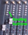 Studio mixers have additional features designed for multi-track recording which normally you would think were not needed for a church service but they can be exploited to solve the problem above. How they work is that each input channel has a set of routing buttons to direct the signal either to the main mix or one or more recording tracks (called groups). There are usually four or eight in stereo pairs so there are three or five routing buttons including the main “mix” routing.
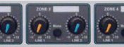
 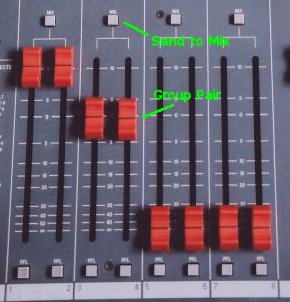 Further across the desk are a set of group faders, usually in pairs, which control the master output level to each track. You can see from this how a multi-track tape recording is made. The feature that makes it useful for our application is that each group output or pair also has a “send to mix” button which does exactly what it says—sends the group output to the main mix controlled by the master fader(s).


 Webmaster