A common fault with these keys is that one of the buttons stops working. You can tell when this is a fault with the key rather than the car because the led stops flashing. If both buttons have failed then first try the obvious and test the battery and make sure the contacts are clean. If so then you need to resort to one of two drastic solutions; buy another one (about £130) or repair it.
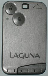
This is the type of key we are talking about, it is the type with two buttons and the safety slot in the end, not the proximity type. There may be other models that use a similar key, I have seen one with three buttons for instance, but I don’t know if they have the same weakness. The fault with these keys is that they use surface mount micro-switches and the “lock” one seems to be on a vulnerable part of the board which perhaps flexes and it drops off. Often you can hear it rattling loose inside.
The tools you will need are a good strong Stanley knife, a soldering iron with a very small tip (1mm or less), some long or curved-nose pliers, a strong magnifier and some super-glue.
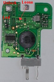
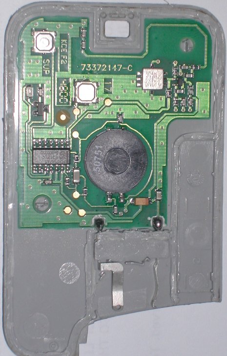
The first task is to get inside. These are not clip-together cases, they are glued all round and on some internal ribs as well. On the photograph of my one below (click for a larger image without my annotations), I have marked the glue lines in red. The blue dots are unglued guide posts. With a strong Stanley knife and starting at the point marked “A” you can carefully cut along the edge, try to cut if you can as it doesn’t split very well—and watch your hands as the blade is liable to slip. When you reach the first bend “B” go back and do the first internal rib, then you can move round peering in the crack to see what to cut next. Be careful not to damage the components or the circuit board. A close inspection of the pictures shows the things to avoid, it is really a matter of patience, care and brute force.
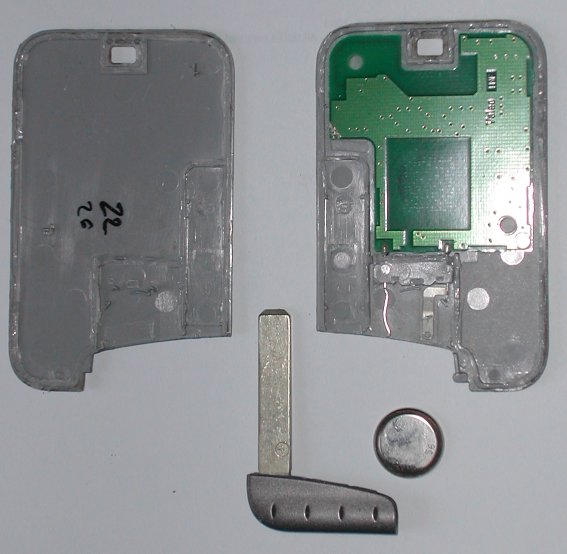
As you can see, mine opened upside down, so the next step is to cut under the battery clip to separate the circuit from the case; I used a small kitchen knife to get in there.
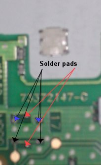
So you should now have all the parts laid out including a loose button switch. This switch has a contact on each corner, two fold-under lugs to hold it together and two other lugs to help it stick to the board (ha! ha!). Sorry, the resolution of our camera is not good enough to see this detail. Near the centre of the circuit board you have a corresponding space with two pads on the earth plane at the top (arrowed blue), two on a track leading to the IC at the bottom (arrowed black) and two isolated holding pads (arrowed red). The orientation of the switch is important, the wrap around lugs MUST be to the sides.
With your fine tip soldering iron, clear up and tin all the contacts on the switch. Similarly clean the circuit board pads. You are well away from any delicate components here so there is not a lot of risk. Make a small solder bead on each pad. When I say small I mean small; I used a jewellers eyepiece to see what I was doing, scary with a hot soldering iron inches from my face.
Now lay the switch on top and test that it works by holding the battery in, and pressing the button. If you get the switch the wrong way around, the light will be on without pressing the button. Satisfied that it works you can solder the switch into place—holding the switch down with long pliers, touch the soldering iron to each corner and the top/bottom edges to get the solder to bridge the gap in six places. You may need to go round more than once as the component beds down to the surface. Test it again. As a final touch, I dribbled a bit of super-glue under the switch as an attempt to hold it more securely.
Now clean up the plastic parts with a knife, removing all loose bits and get the halves to mate together tightly without the circuit. You will also need to clean up the plastic part of the battery clip. Lay the circuit into the back cover, there should be two positioning pegs to hold it in place. Apply a drop of glue to the battery clip to secure it and leave it for a few moments to set. Finally run a bead of glue around the outside edges and the main internal rib, bring the parts together and clamp (clothes pegs) or weight it until it sets. How many of the original lines you do depends on if you are likely to want to undo it again but I would suggest omitting the front of the battery clip.
For the technical, the numbers on the components are: the big round piece (transmitter coil?) is 50751, the DIL package (encoder?) is Phillips PCF7947AT with other numbers 16793102 and DnD00350. The small silvery unit (oscillator crystal?) has EPC05, R727 and M5MN. A Google search didn’t turn up much.


 Webmaster
Dave, I was a bit brief in my comment 133. Yes, the mechanical lock on the passenger side only unlocks that door. To open the rest you need to operate the button on the central console.
I just used your description to successfully fit a replacement ‘lock’ switch to a Launa 2-button key card.
Bought a 2nd hand Lagina Diesel for my step son… found the _only_ keycard the dealer owned had a broken lock function. When I cut it to bits it was obvious it had been dismantled and repaired before yet it was _totally missing_ the lock switch. So someone cut it open, removed the loose switch and glued it together. One word for that, starts with B and has 7 letters.
Had to buy a new one from Renault, cost about £150 plus £60 to program to the car. I wasn’t prepared to hack the only lock card to bits.
Meant I was in the position like others of finding a replacement switch to repair the busted card. Found someone on eBay who was selling 5 of them… so I now have 4 spares! What I looked for was described as a low profile tactical switch, Surface Mount 5 mm square and 1.4 mm high. Fitted it after a bit of fiddle, superglued it all back together and … now both buttons work. Super, saved buying a second card for £210 fitted and working.
RS and Electrovalue don’t sell the switches. Far too unused for Maplin to sell. It was eBay or buying a thousand from China!
Any idea where I can pick up some of these switches??
Pat – see the comment before yours (#142)
Great Rick.
Thanks
Manoj
Thanks for such a helpful Site. Fixed my Espace card instead of binning it! Cheers. Don
cheers mate ive done all you said and the buttons are clicking perfectly,ive tried 3 new batterys and still the LED light dosent work the card starts the car but will not open or lock it.any ideas ? Geoff
if anyone lokin for the swithes i found them on ebay heres the link.
http://cgi.ebay.ie/Renault-Key-Card-Switches-Buttons-Repair-/130525685360?pt=UK_CarsParts_Vehicles_CarParts_SM&hash=item1e63efe670
Hi can anyone tell me if there is any components fitted above the lock switch and to the right of the unlock switch, next to the hole in the plastic part of the key, I think i may have cut them when opening the case up
thx Simon
Hi, thanks for your detailed guide. I have just finished repairing a key card for a neighbour with your help. It wasn’t just quite as straight forward as soldering a switch so im sharing some extra info in hopes it may help someone else.
The casing is much easier to cut if heated up well first with a hairdryer, simple and effective 🙂 The unlock switch on his was attached and working but the circuit track was broken somewhere under the black IC chip. A thin wire soldered from the pin on bottom left corner of the switch to the pin on the bottom right corner of the IC got it working again nicely.
Thanks again for your webpage, it was a great help knowing where to cut and what to expect.
Paddyman
Thank’s for the information it saved me £280 pounds for a new key from renault in Ipswich.
£280! Surely that is for two.
hi this was really useful to me to fix my renault key card. the key card was in my trousers and i put it to wash. then not worked. i opened and cleaned all soap and then put it back. it worked. thanks for explaining how to open the key card. saved me big money.
Thanks for your help on this. There is a service for fixing these but you need to send off your fob and if you’ve only got one (like me) that means you can’t drive your car until it’s returned. So I bit the bullet and had a go. It was great to have your advice especially the orientation of the switch. Wish I’d seen your site before I broke it open though as I made a mess. Didn’t know I’d have to use a stanley knife. Found your page after a search because I couldn’t get the bat compartment away from the cover. Anyway. Thanks again. Just a word of caution though BE CAREFUL WITH THE STANLEY KNIFE – I cut a deep chuck out of my thumb and it wont stop bleeding. 🙂 At least I got my lock working again.
Sorry, forgot to leave the link. It costs £25 to have your card fixed. here is the link: http://www.keyrepair.co.uk
Thanks for this great information. I just saved £150. I managed to open my key-card and solder the micro-switch back it its place. It had fallen off and the lock button was not working. I didn’t need any magnifying glass or special pliers or any special tools. Just a lot of patience and care. Opening it was particularly challenging but the images here helped a lot.
Firstly, a big thank you!
Didn’t have a soldering iron or a Stanley. I had to use a flat head screwdriver with bruit force to prise the covers semi apart… Sure enough, the switch button fell out.
Not having a soldering iron, I thought I was out of luck. However, I placed the button on top of the old placements. Leaving the battery in, tested button and the LED flashed. So, with a little hope, I simply used glue to hold the button inplace. When pressed through the top cover, there is enough pressure to make it work.
I suggest soldering it obviously, but this works as a temp fix if you have the loose button.
Thanks, Ry
hi there ! good work on your blog – your helping to make life easier for many people ! 😀
I have what seems to be a dead battery on my koleos (3 button type card) key card,
and saw the card was not easy to get open, it seems for a simple battery replacement
– i till have to prise or cut the thing open ?
Is there no simple method for just replacing the battery ?
cheers
daniel phillis
http://www.danielphillis.com
Hi Daniel – I haven’t seen a three button card but my Megane, like the new Koleos card has four. I would be surprised if you can’t get the battery out to replace it without cutting it open. On the two button ones the battery slides out when you remove the emergency key. On the four button ones it is harder – first remove the emergency key (by pressing the little button on the side and pulling). Then use the end of the key to prise the circular cover off the back and the battery is underneath (it is very stiff).
Excellent advice and post. It took me 30 minutes and £15 t for a soldering iron and solder to do .